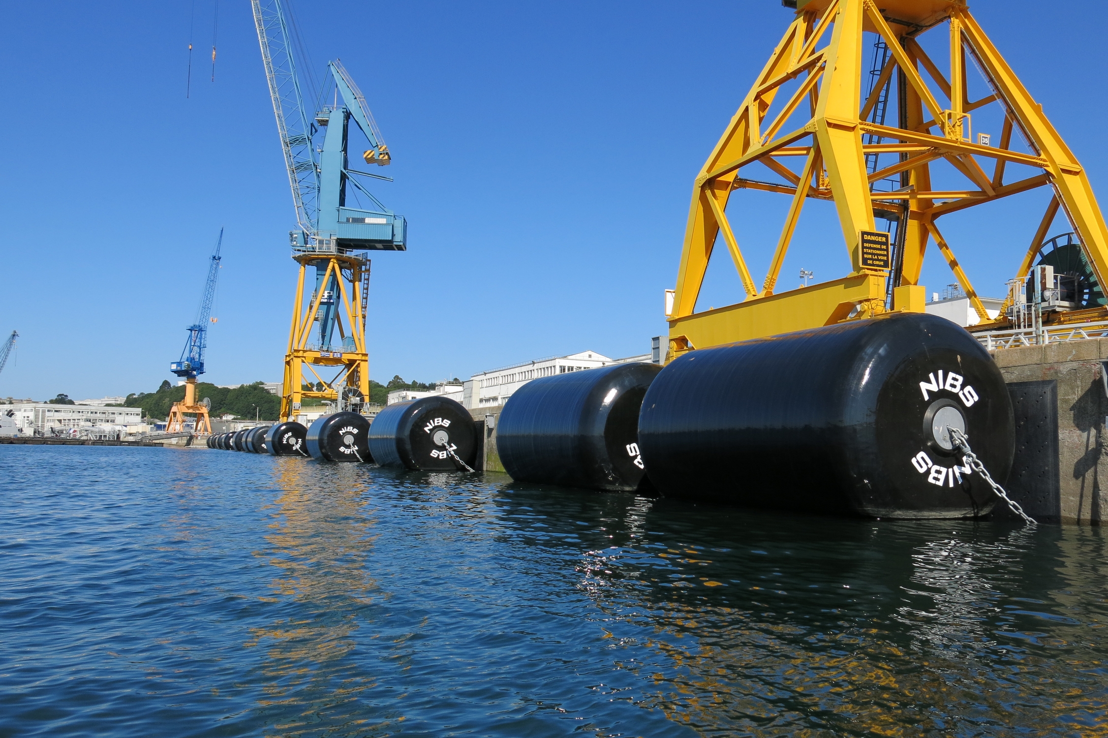
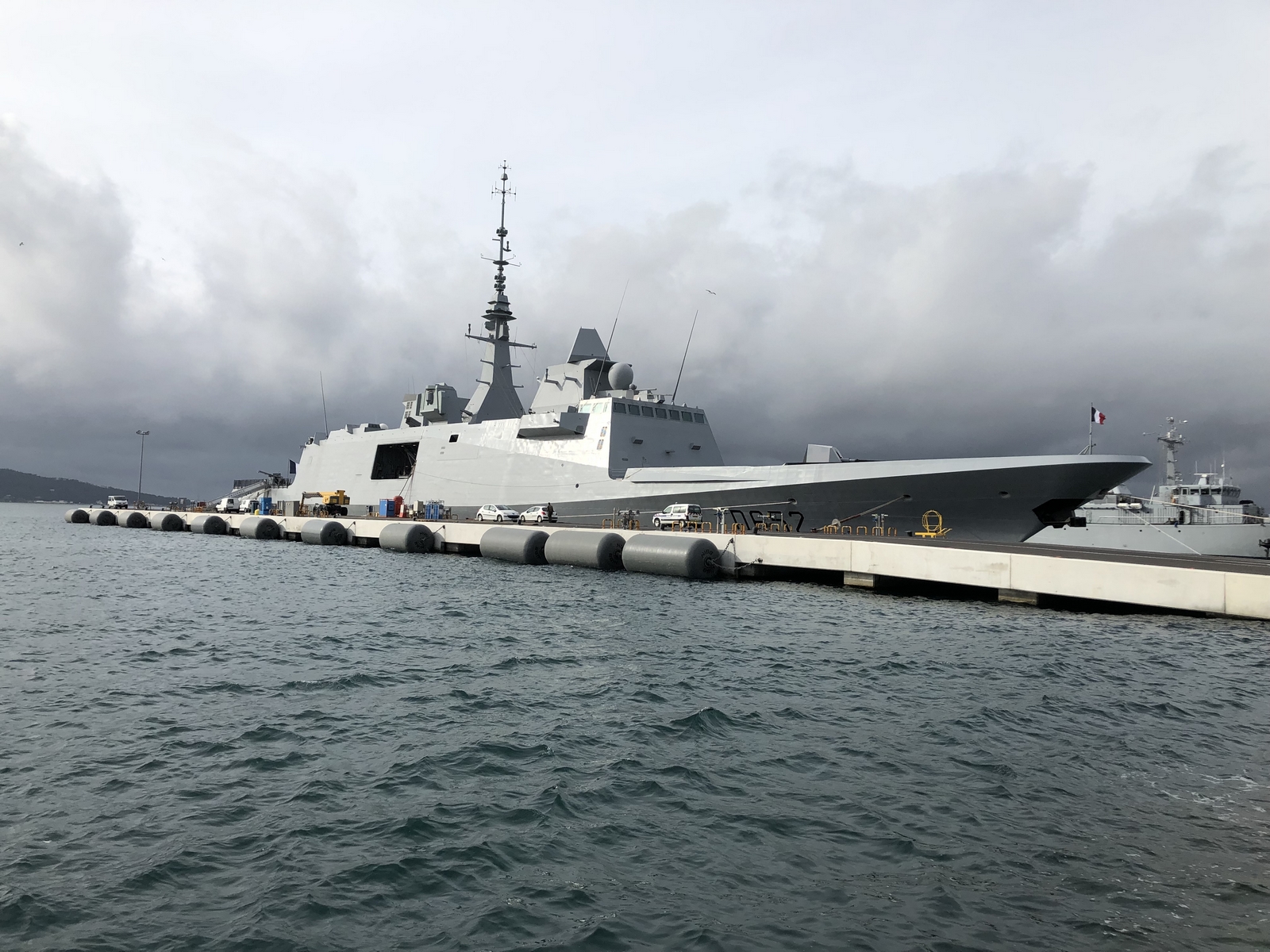
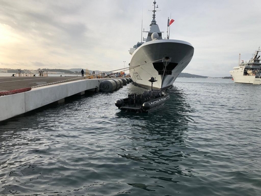
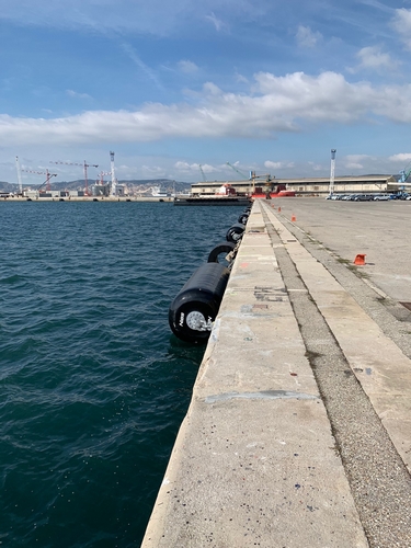
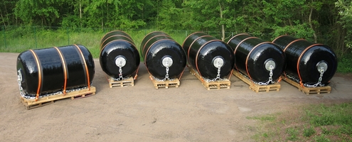
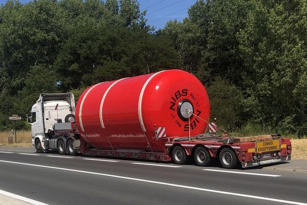
Quayside foam filled fenders
Calculating the berthing energy of vessels is the first and most important step in the fender design process. If something goes wrong during this step, your entire waterfront design could be at risk. As part of the many services we offer our clients, our new software supports you during the berthing energy calculation process. Our software considers all relevant parameters such as :
- Ship type,
- full load vessel weight,
- berthing mode,
- or point of contact from bow, amongst others, and also offers the option to choose among different design methods, addressing the particulars of your project and or region.
Designed by our engineering office, based on a heat laminated 100% closed cell polyethylen (PE) foam, wrapped with high tenacity polyester fabrics, coated with hot laminated polyurethan and embedded end fittings.
Excellent *energy performance and coupled with low *reaction force makes berthing operations easier especially in difficult conditions.
- *Energy absorption = fender’s ability to dissipate energy generated from berthing
- *Reaction force = Strength/Push ratio, generated by the compression of the fender during berthing taken by both the dock & vessel hull
The floating foam fenders are very appropriate for dock, especially dock with large tidal range.
The foam fenders are available in diameters from 700 to 4500 mm and lengths from 800 mm to 15000 mm.
Different foam density, from 30 to 140 kg/m³ are available upon request.
Foam filled fender performances
| Ø x Lg (m) | Extra soft(30 kg/m³) | Soft (50 kg/m³) | Medium (70 kg /m³) | Hard (100 kg/m³) | Extra Hard (140 kg/m³) | |||||
| Energy (T.m) | Reaction (T) | Energy (T.m) | Reaction (T) | Energy (T.m) | Reaction (T) | Energy (T.m) | Reaction (T) | Energy (T.m) | Reaction (T) | |
| 0,70 * 1,00 | 1,50 | 9,20 | 2,20 | 13,70 | 2,40 | 15,00 | 3,20 | 20,45 | 4,35 | 27,85 |
| 1,00 * 1,50 | 4,45 | 19,75 | 6,60 | 29,45 | 7,20 | 32,20 | 9,75 | 43,95 | 13,30 | 59,80 |
| 1,50 * 3,00 | 20,10 | 60,00 | 29,80 | 89,35 | 32,60 | 97,70 | 44,30 | 133,30 | 60,40 | 181,50 |
| 2,00 * 4,50 | 53,65 | 120,50 | 79,70 | 179,35 | 87,15 | 196,15 | 118,40 | 267,60 | 161,60 | 364,30 |
| 2,50 *5,00 | 92,80 | 166,75 | 137,85 | 248,20 | 150,75 | 271,45 | 204,80 | 370,35 | 279,50 | 504,15 |
| 3,30 * 6,50 | 210,00 | 286,00 | 312,05 | 425,70 | 341,20 | 465,60 | 463,65 | 635,20 | 632,75 | 864,70 |
Fittings
- Link flange (+ 3D screenshot)
- Gusset flange
- Swivel flange
- Commercial swivel flange
- Rotating link flange
the choice of mooring method depends on several key factors such as ;
- Port tidal range,
- compression angles,
- Longitudinal movement of ships berthing at moorings,
- Surface area available on the berthing point,
- Abrasiveness & flatness of the face of berthing area,
- accessibility for maintenance,
- the height of the waves in relation to the dimensioning of the defense
Installation lay- out
There are different installation options available
- Simple floating mooring, fixed with properly dimensioned chains according to tidal movements to the quay,
- Suspended mooring, the quay height must be higher than the mooring surface. Fixation by chain is required to prevent the fender rolling onto the top of the quay when tide is high or variation of the vessel draft varies.
- Mooring with tidal monitoring system, concerning areas with high tides, a guide rail is installed on each side of the foam filled fender connected to a mooring ring
Features of foam filled fenders :
- Unsinkable
- Bespoke dimensions
- Proportional increase of energy & reaction
- Low hull pressure
- Non marking finish
- Low maintenance
- Long life expectancy
- Repairable
- Respect of environment
- Available in different colours
- Anti-UV treatment available upon request
Applications :
- Navy base & cruise terminals
- Oil&Gas terminals
- Port Harbour
